Vitro Shard Edge
Vitro Shard Edge
Vitro Shard Edge (v1.0) is an Open Hardware carrier board equipped with multiple industry interfaces (e.g., RS232, RS485, ADC, Current Loop, CAN) and low-level embedded interfaces (e.g., GPIO, UART, SPI, I2C) with a mPCIe slot designed for Vitro Shard (on J20 port). Vitro Shard Edge extends the operation of the Vitro Shard device and easily provides multiple interfaces to the user, allowing it to attach sensors and communication channels.
Overview
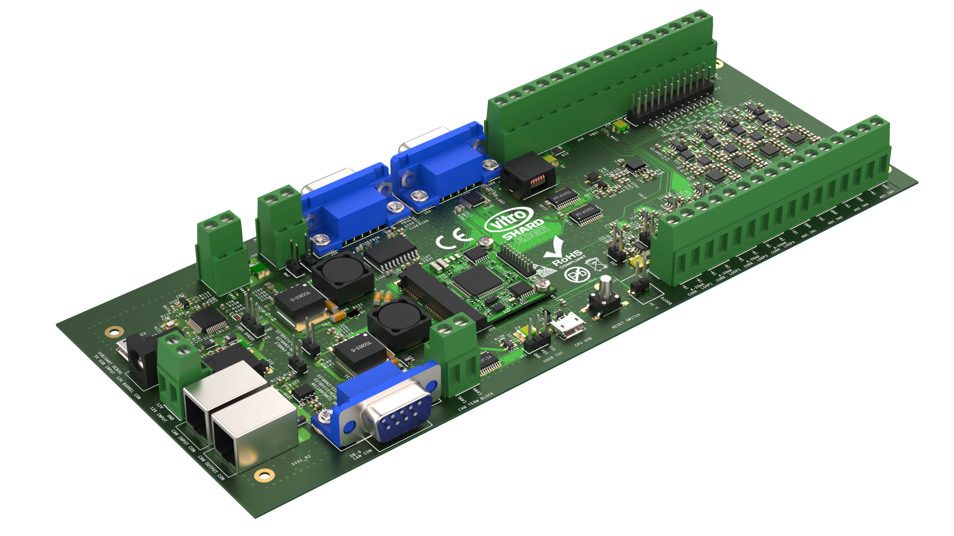
Vitro Shard Edge board
Vitro Shard Edge has many possible applications due to many available interfaces. It has:
- 10x GPIO available on 2.54mm pin header (J13). This header is also connected to ports J14 to J19.
- 4x analog input channel (0-30V capable input - with input voltage range selection between 0-5V, 0-12V, 0-20V, 0-30V, 0-36V), accessible on ports J1 to J4.
- 4x current loop channels (4-20mA current measurement) on ports J5, J7, J9, and J11.
- RS-232, RS-485, CAN, I2C, UART, SPI, and USB-OTG interfaces.
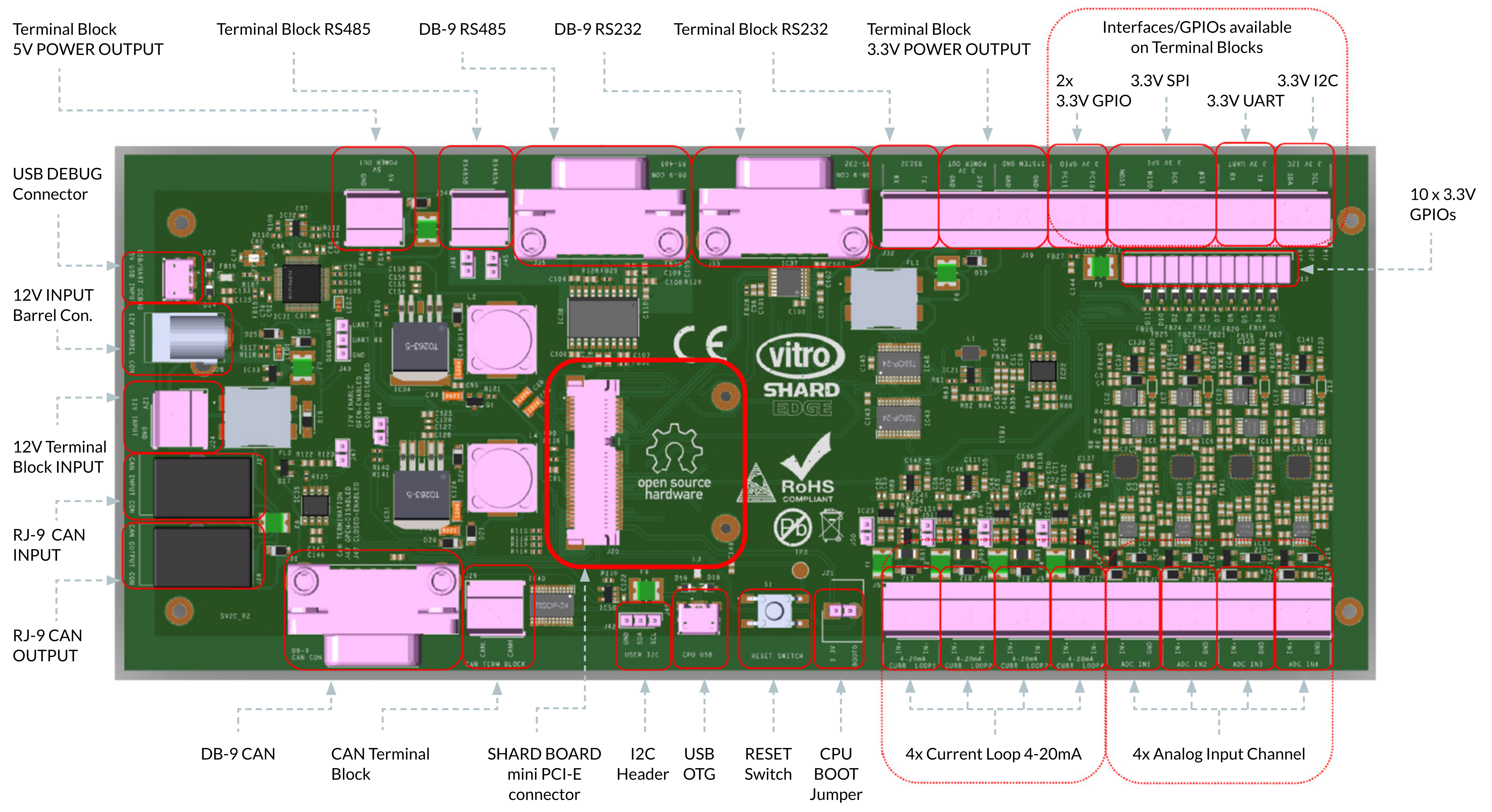
Vitro Shard Edge connection
There are also some ways you can power on the board:
- 12V input: DC barrel connector (J26), terminal block (J24), and RJ12 connector (J55 on pin
1and2). - 5V input: USB Debug connector (J54).
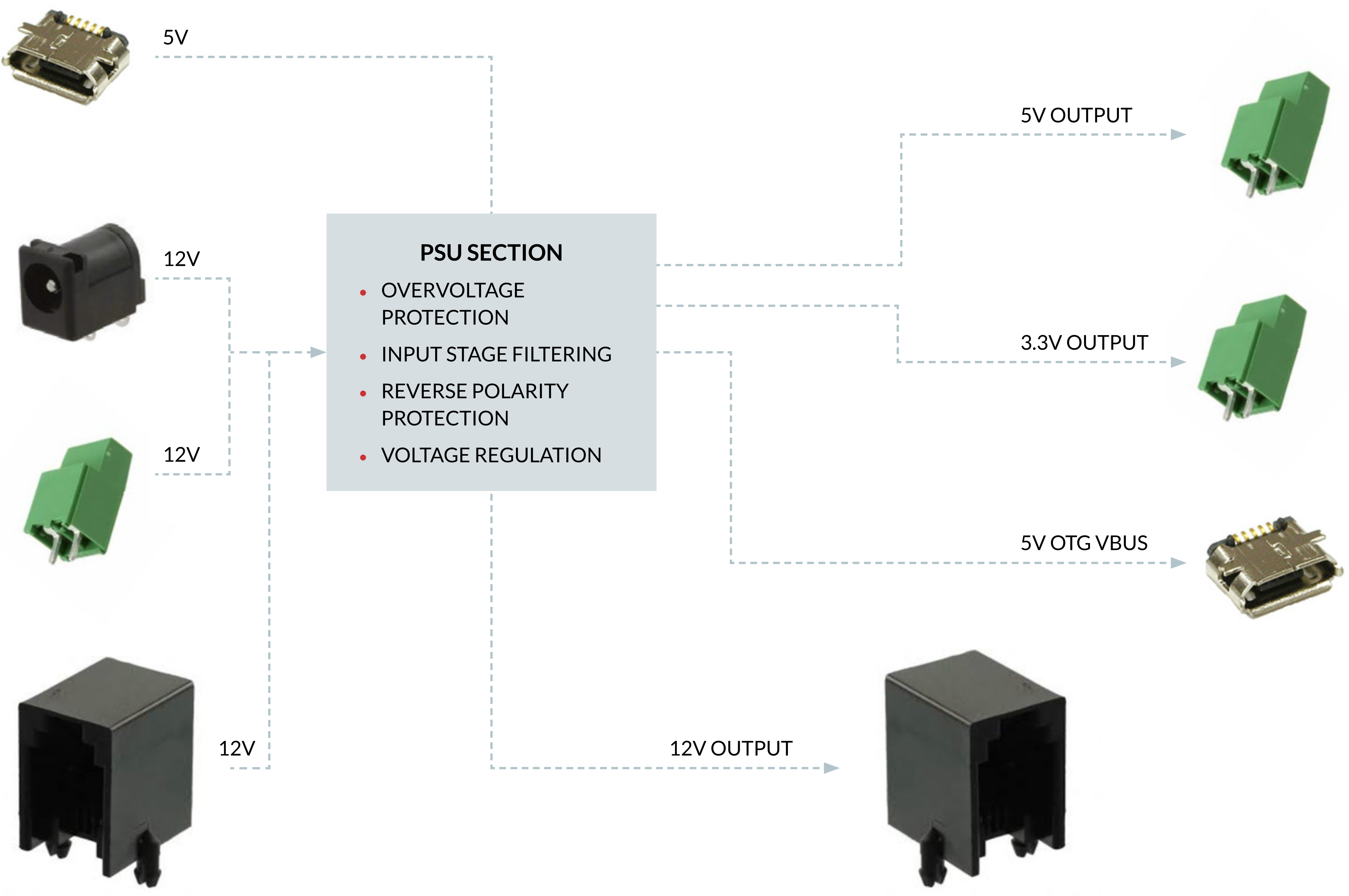
Vitro Shard Edge power supply connections
As an Open Hardware board, the schematics are readily available here.
Specifications
These specifications assume that Vitro Shard is present in the mini-PCIe slot.
| Name | Description |
|---|---|
| Microcontroller | ARM Cortex-M4 STM32L4 @ 80 MHz |
| MCU Memory | 1 MB (1M x 8) FLASH |
| Security IC | ATECC608A-MAHDA-T |
| USB OTG | 1 |
| CAN Bus | RJ-12, DB-9 and Industrial Screw Terminals |
| RS-485 | DB-9 and Industrial Screw Terminals |
| RS-232 | DB-9 and Industrial Screw Terminals |
| Status LEDs | 2 |
| I/O | RESET Button |
| I/O | 10x I/O Pins (GPIO/I2C/SPI/UART) |
| I/O | 3 Pin UART Header |
| I/O | 3 Pin I2C Header |
| I/O | 4x 4-20mA Current Loop Inputs |
| I/O | 4x 0-30V ADC Inputs |
| Power Input | 12V DC@1A or 5V DC @ 0.5A (micro USB connector) |
| Temperature Range | Commercial: 0°C to 85°C |
| Temperature Range | Industrial: -40°C to 100°C (optional) |
You can also check the Vitro Shard Edge block diagram:
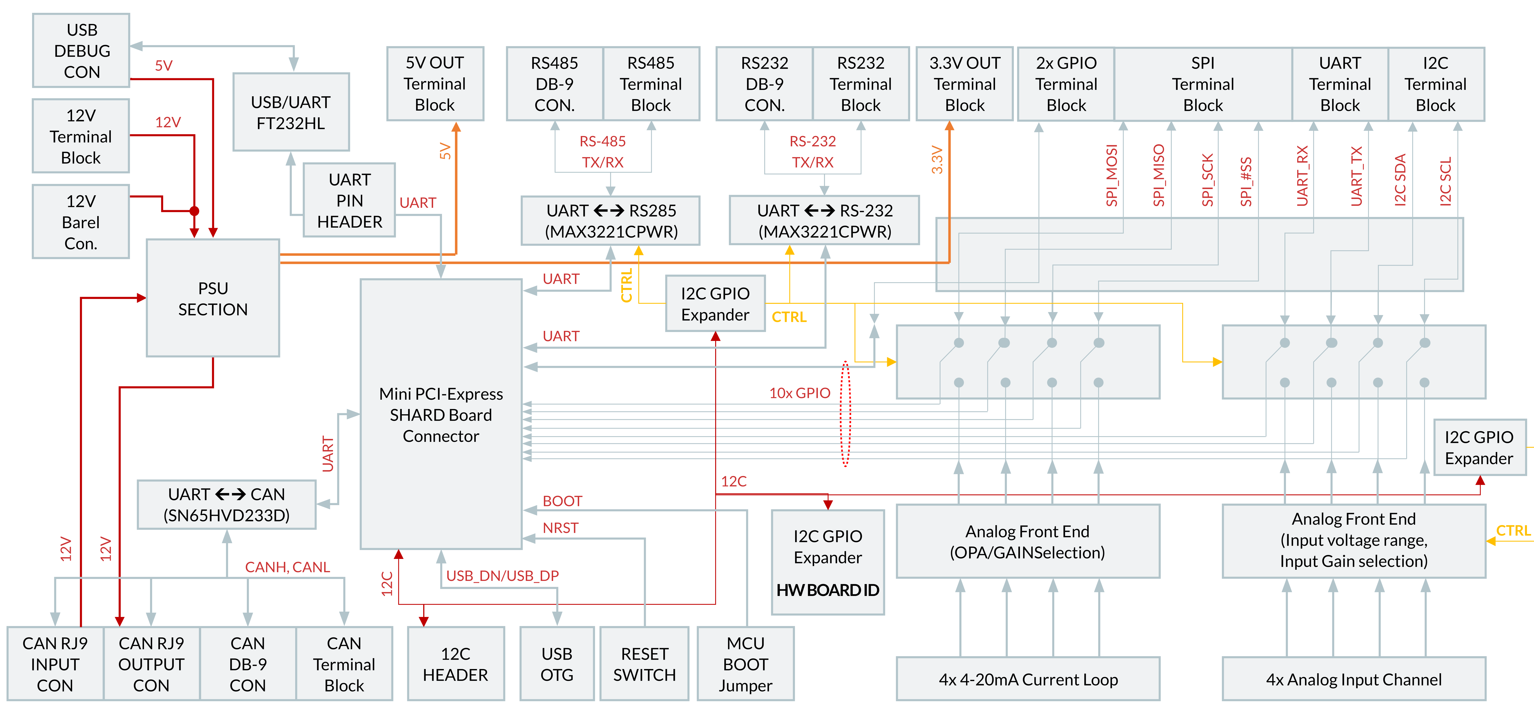
Vitro Shard Edge block diagram
Sensors' Connections
This section focuses on how to connect a sensor on Vitro Shard Edge. It describes the connection guide for three types of sensors:
- DHT22: Temperature and humidity sensor.
- MCT-0016-XXX: Current sensor.
- LDR Sensor Module: Light sensor module.
To showcase the Vitro Shard Edge I/Os connectivity, please check the image below:
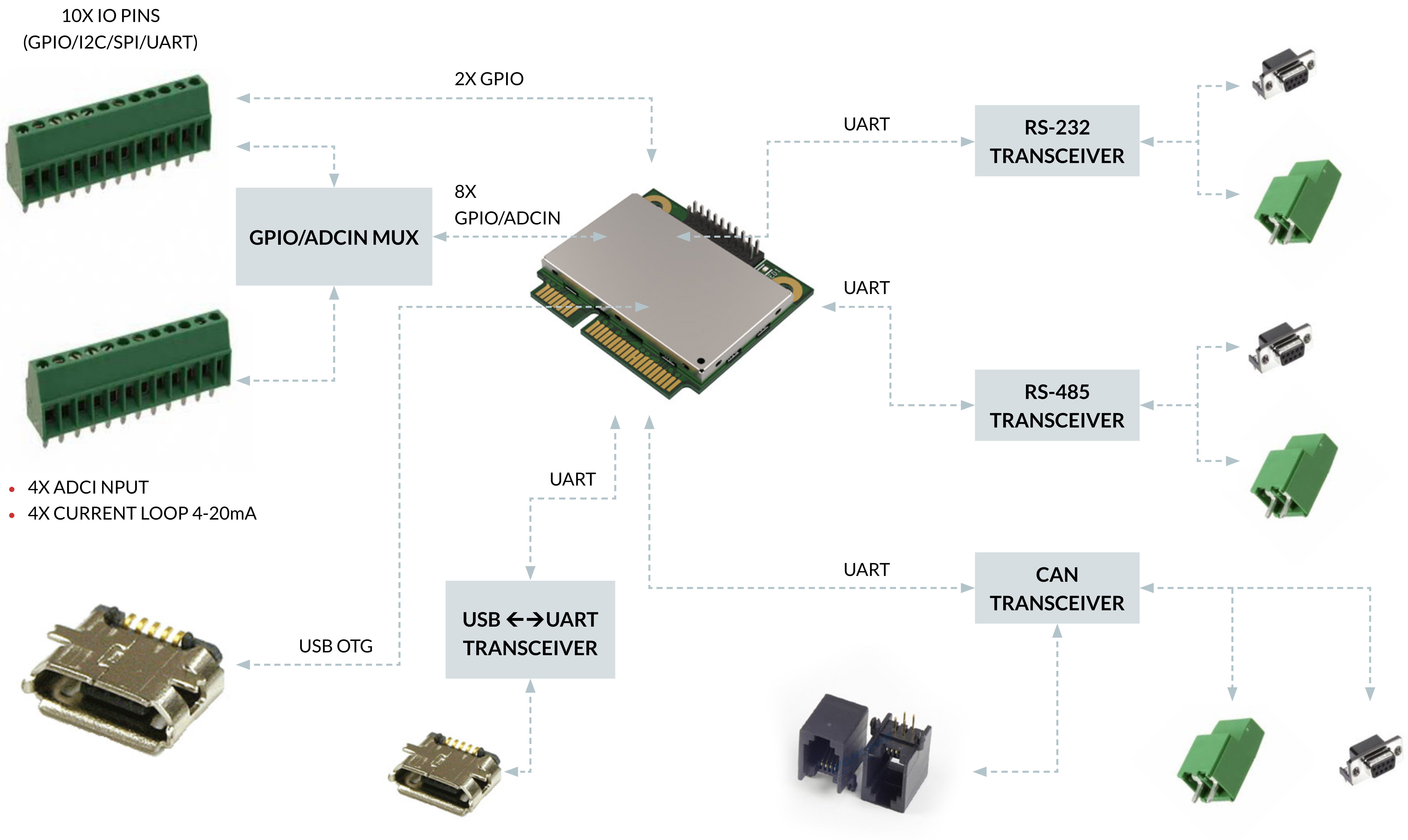
VItro Shard Edge I/Os connectivity
DHT22 connection
The DHT22 is a temperature and humidity sensor. It has four pins: power supply (VDD), data, NC (no-connect), and ground (GND). According to its datasheet, it needs between 3.3V to 6V on the VDD pin. This means that we can connect the sensor the following way:
- The GND pin can be connected to any GND port on Vitro Shard Edge.
- The VCC pin can be connected to a 3.3V or 5V port on the board.
- The NC pin is not used.
- The DATA pin can be connected to any GPIO port that is not being used.
Therefore, one possible connection is shown in the diagram below.
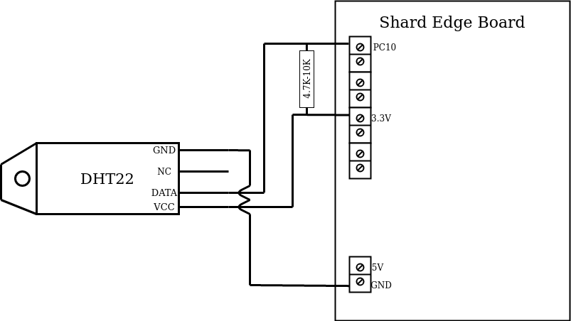
DHT22 connection diagram
Notice that there is a resistor there ranging from 4.7k to 10kΩ. This is optional, but recommended for reliable operation. Thus, as an example, you can connect this way (no breadboard required):
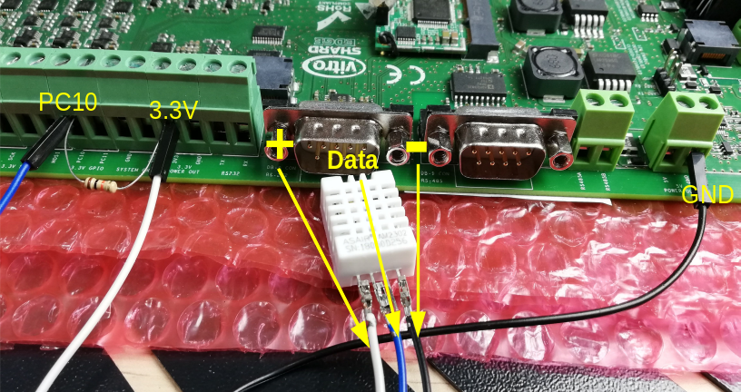
DHT22 connection with the resistor
However, there are DHT22 sensors mounted on a PCB. If this is the case, you don't need to add the resistor, as it is already soldered on the sensor's board. If this is the case:
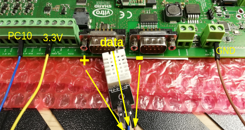
DHT22 with PCB connection
LDR Sensor Module connection
The LDR Sensor Module comprises an LDR sensor, an LM393 comparator, and a 10kΩ potentiometer. Due to the comparator, this module is sometimes also called the LM393 sensor module. The module has two versions: with or without the analog pin. Thus, the pinout is:
- The GND pin can be connected to any GND port on Vitro Shard Edge.
- The VCC pin can be connected to a 3.3V or 5V port on the board.
- The D0 pin can be connected to any GPIO port that is not being used. Its output is a digital signal (either 1 or 0), where 0 is for high light intensity and 1 for low.
- (Optional) The A0 pin can be connected to any GPIO port that is not being used. It outputs an analog signal that is inversely proportional to the light intensity.
The circuit is straightforward. Basically, the LDR is connected in series with a resistor acting as a voltage divider. The voltage applied on the LDR is then sent to the LM393 comparator (non-inverting) and the A0 pin. The inverting side of the comparator has the potentiometer. The potentiometer then sets the threshold voltage (you can change the threshold by changing the resistance). If the voltage on the LDR is higher than the threshold, then the comparator output is 1 (high), and the D0 pin reads this value. Otherwise, it is 0 (low).
For completeness sake, the LDR used on the module can change. Furthermore, its resistance range also varies according to model, ambient temperature, and other variables. As an example, you can check this datasheet to understand it better.
As a rule of thumb, you either read pin A0 or D0. If you read A0, you measure the voltage applied on the LDR. It is possible to obtain the lux by calculating the LDR resistance (as the resistor and voltage input are known) and calculating the gamma characteristic as shown by the datasheet. Or you can code your threshold (if statement) instead of using the potentiometer. Regarding the D0 pin, you will need to calibrate it. This can be done by first reading its value, setting the light intensity desired for the threshold, and then changing the potentiometer until the output is right where it changes from 0 to 1.
In this example, the sensor module has only the D0 pin. A possible connection is shown below:
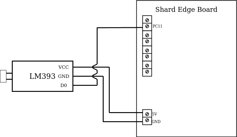
LM393 connection diagram
It should look something like this on the board:
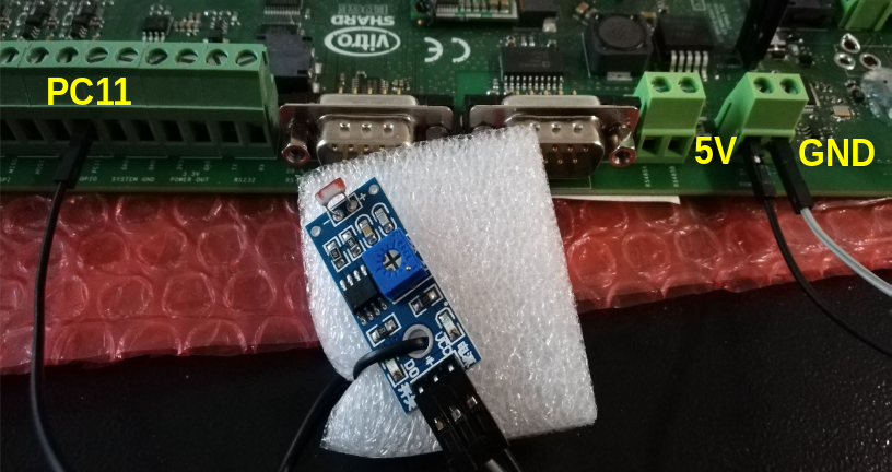
LM393 connection
Notice that the connection for this module is compatible with the DHT22 one, i.e., they are not using the same port (except for the GND, but you can change it to another GND port).
MCT-0016-XXX connection
The MCT-0016-XXX is a current transducer. It measures input up to 100 Amp AC and a 4 to 20 mA DC as output. The transducer also needs a 20 to 30 V DC power supply. Lastly, we also need a maximum 600 Ω load resistance. For more information, you can check its datasheet.
The XXX means that it changes accordingly to the ratings. There are five different ratings available: 5, 10, 20, 50, and 100 Amp. For example, for the 5 A rating, the device part number is MCT-0016-005.
We can use the Current Loop (CL) from Vitro Shard Edge for measurement taking as we have a current output from the transducer. The connection between the sensor and the CL should look like this:
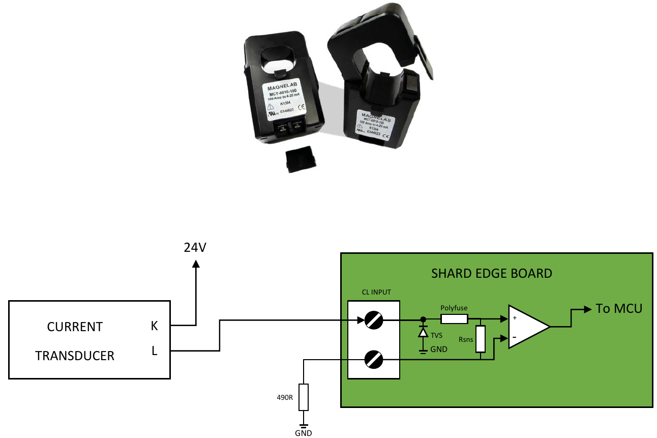
MCT-0016-XXX connection diagram
You can start by attaching the input and output cables on the CL:
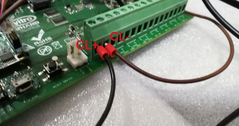
CL connection
The CL schematic is located on page 7 of the Vitro Shard Edge's schematic.
The sensor should be powered by a power supply (20 to 30 V). It is possible to use a laboratory power supply. Therefore, connect the positive side to the K screw of the transducer. The L screw is the sensor's output, which the CL will measure. Thus, we connect the L screw to the CL+ port.
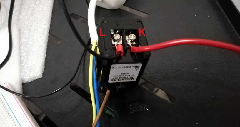
Transducer connection
The CL- port is the CL's output. Remember that we need a load resistance of up to 600 Ω. In this example, it is used a 480 Ω one. Thus, you connect the CL- to the resistor and the resistor to a Vitro Shard Edge GND pin. Finally, connect the power supply's ground cable to a Vitro Shard Edge GND pin.
To better illustrate, the two images below showcase the connections required:
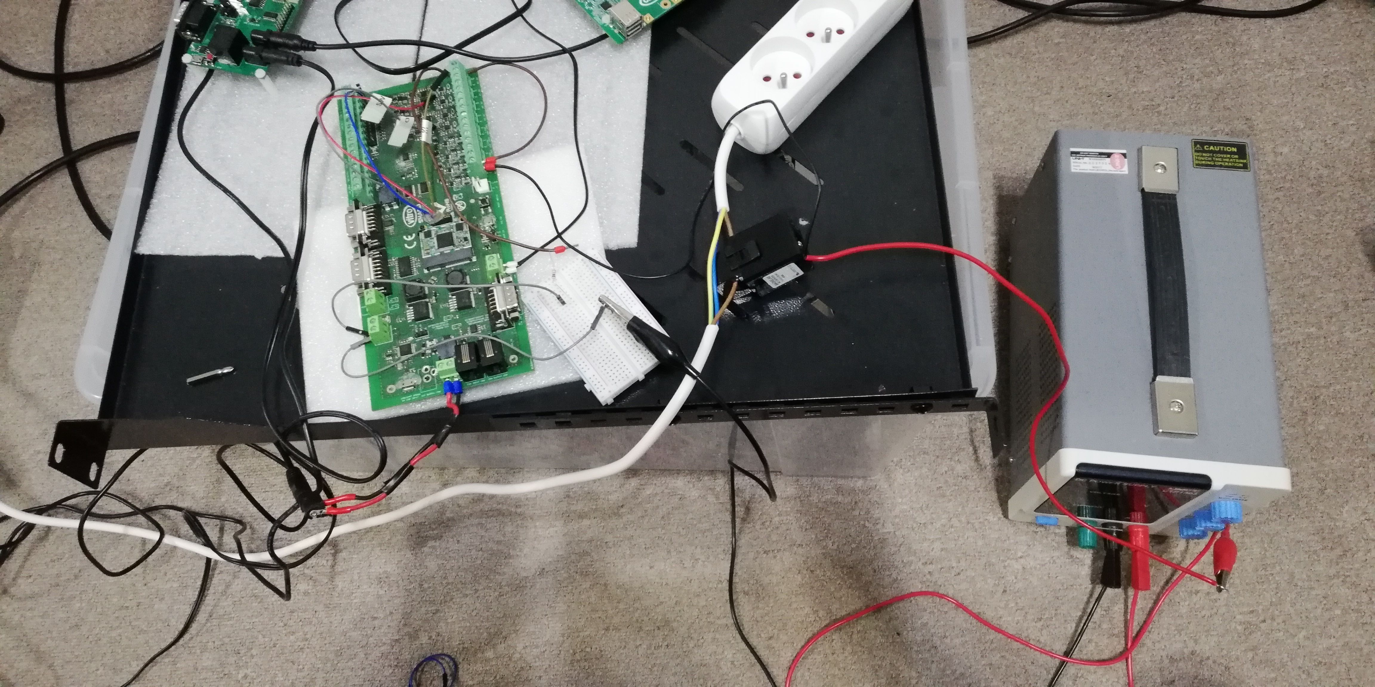
Transducer connection overview
Zooming into the resistor:
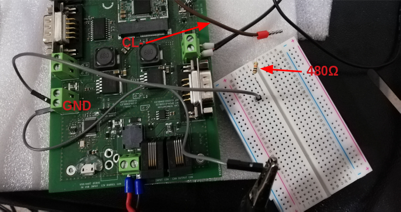
transducer resistor connection
To correctly make a measurement, the sensor must be tightened around the alternating current's phase conductor to work properly.
Updated 9 months ago
