Vitro Crystal (v1.0)
Vitro Crystal (v1.0)
Overview

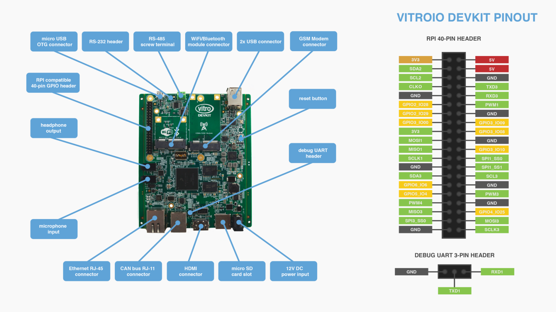
Vitro Crystal Board and headers.
Vitro Crystal has many available features that allow for a reliable and secure operation. First, it accepts many interfaces: USB, UART, I2C, SPI, RS-232, and RS-485. It also provides a simplified sensor monitor and control via SCADA, CAN bus, MOD bus, PM bus, and more.
The board supports Ethernet, Wi-Fi, Bluetooth, GSM, CDMA, LoRa, Sigfox, and more for network redundancy. To provide secure communication with Vitro Cloud Infrastructure, Vitro Crystal also comes with private keys stored in hardware. Furthermore, the board also accepts Over-the-Air updates.
It also has hardware-accelerated H.264 video compression and a 1080p@24 fps HDMI output. Thus, it can also be used as a stand-alone media center.
Finally, Vitro Crystal supports the custom Yocto-based OS. It is dedicated to IoT Block-based applications, stands as a gateway in the IoT Block communication pipeline. Vitro Shard and Vitro Shard Edge are end-device connected through one of the transport protocols.
MCU
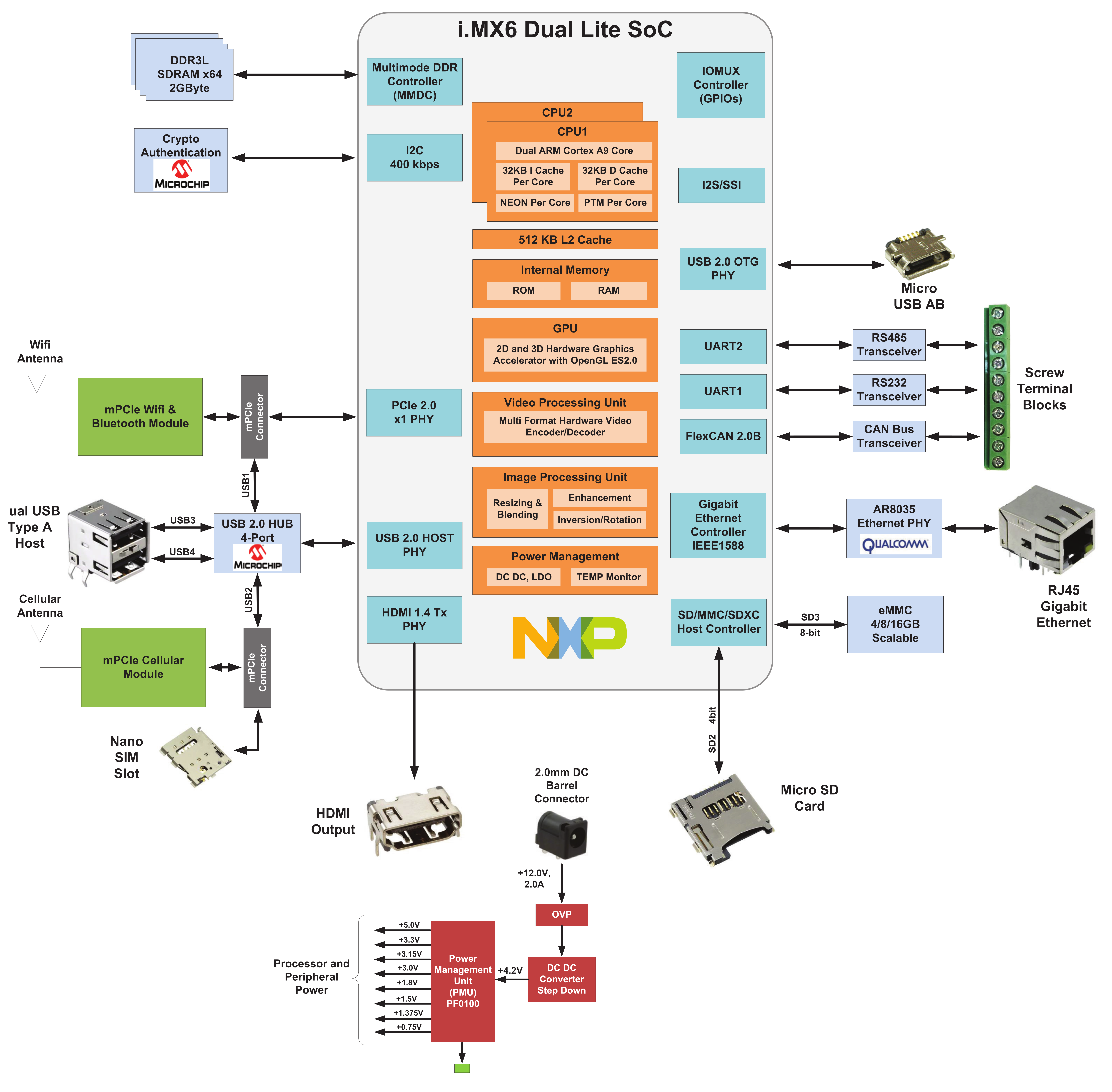
The Vitro Crystal's microcontroller is a NXP i.MX 6DualLite, which is based on ARM Cortex-A9 MP Core. Its diagram is shown by the following image:

MCU diagram.
ECC
The ATECC508A has ECDH (Elliptic Curve Diffie–Hellman) key exchange, and ECDSA sign-verify capabilities built-in to provide highly secure asymmetric authentication. Furthermore, the chip employs ultra-secure hardware-based cryptographic key storage and cryptographic countermeasures, which are more secure than software-based key storage.
ATECC508A also has SHA-256 hash algorithm with HMAC support, 256-bit key length, and stores up to 16 keys using a 10 Kb EEPROM (stores certificates and data too). This essential chip authenticates the device's ID and provides many security-focused features, e.g., secure boot.
Details
Vitro Crystal also has many I/O. The first one is the UART header (J14). The pins are, in order: GND, TX, and RX. There is also a JTAG header (J6) next to the UART. The board also has a Raspberry Pi HAT compatible header (J17 header).
You can also boot from the Micro SD Card (J1 port) or the 8GB eMMC. To do that, you need to set the pins on SW2 correctly. To set a pin to 1, you need to slide the pin-up (i.e., in direction to the mPCIe port), while to 0, the opposite (i.e., slide it down in the Micro SD Card direction). Therefore, to configure the board to boot from the Micro SD Card, the configuration table is:
| Switch number | 1 | 2 | 3 | 4 | 5 | 6 | 7 | 8 |
|---|---|---|---|---|---|---|---|---|
| Value | 1 | 0 | 1 | 0 | 0 | 0 | 1 | 0 |
If you want to boot from the eMMC flash memory, set the pins as follows:
| Switch number | 1 | 2 | 3 | 4 | 5 | 6 | 7 | 8 |
|---|---|---|---|---|---|---|---|---|
| Value | 0 | 1 | 0 | 1 | 0 | 1 | 1 | 0 |
In order to boot the board, you need to short pins 1 and 2 from the J12 header. In case you need to reboot, you can press the SW3 button.
Specifications
The device specifications are as follows:
| Name | Description |
|---|---|
| Controller | NXP iMX 6DualLite@1GHz |
| RAM | 2GB, 64-Bit DDR800 |
| Floating Point | VFPv3 |
| SIMD | NEON |
| GPU | Vivante GC800 |
| 3D GPU Support | OpenGL ES101/2.0 |
| eMMC | 8GB eMMC flash |
| SD Card | Micro SD Slot |
| Video Codec | Multiple, H.264 |
| HDMI | Audio/Video 1080p@24 fps |
| HDMI Interface | HDMI Type A, HDMI PHY |
| Audio | 2x3.5mm jack for Audio Input/Output |
| Wired Network | RJ45 - 10/100/1000 Mbps |
| Wireless Network | Wi-Fi (Optional) |
| Mini PCIe 1 | Half Size (Wi-Fi/Bluetooth support) |
| Mini PCIe 2 | Full Size (Cellular modem support - nano-SIM) |
| USB 2.0 Host | 2 Dual Stacket Type A |
| USB OTG | 1 |
| CAN Bus | RJ11, industrial screw terminals |
| RS-485 | Industrial screw terminals |
| RS-232 | Industrial screw terminals |
| Status LEDs | 2 |
| I/O | Reset button |
| I/O | Raspberry Pi HAT compatible header |
| I/O | 3-pin UART header |
| I/O | JTAG Test points |
| Power Management | PMIC PF0100 |
| Power Input | 12V DC @ 2A |
| Temperature Range | Commercial: 0 to 85 °C |
| Temperature Range | Commercial: -40 to 100 °C (optional) |
| Regulatory Approvals | FCC, CE, RoHS |
| Packaging | 9x7x2 inches - 12.2 oz. |
| Packaging | 23x18x5 cm - 345 grams |
Updated 9 months ago
